Designing mechanical parts for 3D printing is fundamentally different from designing for injection molding or CNC. The layer-by-layer additive process introduces unique constraints — and opportunities — that directly affect structural integrity and assembly precision. These five principles are what separate a part that performs from one that fails at first load.
Quick Reference
Before diving in, here are the key FDM design parameters to keep in mind: Minimum Wall Thickness: 1.2 mm (3× line width). Max Overhang Angle: < 45° from vertical. Typical Tolerance: ±0.2–0.4 mm. Hole Compensation: +0.1–0.2 mm oversize. Min Feature Size: 0.8 mm. Weakest Axis: Z (Layer Direction).
01 Orient for Load, Not Just Printability
FDM parts are anisotropic — significantly stronger along the XY plane than along the Z axis (the print direction). Layer lines are the primary failure point under tension. Orient features so that tensile loads run along layer lines, not across them.
✓ Do: Align primary tensile load paths with the XY plane. Design flanges across the plate.
✗ Don't: Print thin vertical walls that will be pulled apart across layer lines.
- ~30–50% Z-axis strength penalty
- XY is the strongest load direction
02 Design Holes Oversize — Always
Printed holes shrink. Due to thermal contraction, holes consistently print smaller than nominal — typically 0.1–0.4 mm undersize. For any hole mating with a shaft or bolt, add clearance proactively.
Clearance fits: Add +0.3–0.4 mm to hole diameter. Running fits (bolts): Add +0.2 mm for easy insertion. Heat-set inserts: Follow manufacturer bore spec exactly.
03 Respect the 45° Overhang Rule
Features overhanging at >45° from vertical require support material or will sag. Best design eliminates supports entirely. Use chamfers instead of horizontal lips, and teardrop-shaped holes for horizontal bores.
✓ Self-Supporting: 45° Chamfers, teardrop holes, arched spans.
✗ Support-Dependent: Horizontal lips (>45°), large flat-bottomed holes.
04 Size Walls to Perimeter Multiples
Slicers build walls from perimeter passes. If wall thickness doesn't align to multiples of line width, the slicer uses infill to fill the gap — creating a weak, inconsistently bonded region.
Target wall thicknesses for a 0.4mm nozzle: 1.2mm (Min), 1.6mm, 2.0mm, 2.4mm, 4.0mm (Heavy Duty).
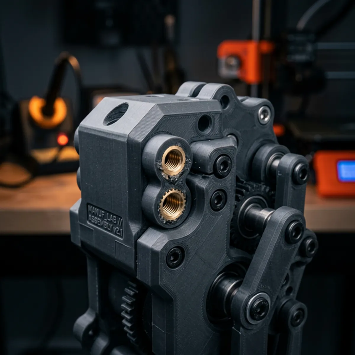
05 Use Heat-Set Inserts for Threads
Threading directly into plastic fails under repeated assembly. Self-tapping screws crack bosses. For any assembly that needs servicing, design for heat-set brass inserts.
Step 1: Design boss correctly — Boss OD ≥ 2× insert OD. Bore = spec. Step 2: Set iron temp ~200°C (PLA) to ~260°C (ABS). Step 3: Press slowly — apply even pressure until flush. Let cool for 60s.
Where These Rules Matter Most
Enclosures with Fasteners: Walls need multiples for strength, holes need oversize clearance, and inserts are essential for repeated opening. All 5 tips apply.
Functional Gears: Load orientation determines tooth survival. Wall thickness determines hub solidity under torque. Tips 1, 2, 4 apply.
Mounting Brackets: Load direction is priority — printed flat is much stronger than on edge. Bolt holes need clearance. Tips 1, 2, 4 apply.
Jigs & Fixtures: Locating holes must be precisely oversized. Clamping points need insert-backed threads. Tips 2, 3, 5 apply.
Frequently Asked Questions
Do these apply to SLA/SLS, or just FDM?
Tips 1 and 4 are FDM-specific. SLA is more isotropic and doesn't use perimeter-based walls. Tips 2, 3, and 5 apply broadly — all processes have shrinkage and need support management.
Can I use thread-forming screws instead of inserts?
For one-time assemblies, yes. But for anything opened more than 3-5 times, inserts are far superior as they won't strip the plastic boss.
Does material choice change these rules?
Significantly. PETG shrinks less than ABS, so hole compensation differs. ABS/ASA warp more, making orientation even more critical for bed adhesion.
Can Atlas3Dprints review my design first?
Yes. For functional assemblies, we offer design review as part of our quoting process. We'll flag tolerance or structural risks before printing.
Ready to Print Your Mechanical Part?
Send us your design and we'll handle the rest — with professional FDM printing, quality checks, and fast turnaround.
Request a Free Quote